Cheat Sheet

If you have purchased your speaker kit after the first of October 2017, we have made some changes and improvements to make the speaker easier to build, and sound better. 


DSC_1640.JPG

Mount the Terminal Bus

The battery will be connected to components via a 3D printed terminal bus, in which loop terminals will be placed onto a bolt and screwed down tight with a nut. 

The terminal bus will have two bolts, one positive and the other will be negative. 

All of the red positive cables with a Loop Terminal, will be wired to one of the bolts. All the negative cables with a Loop terminal will be black and will be wired to the second bolt.

To mount the Terminal Bus - screw a self tapping screw into the hole of the terminal bus and into the MDF wood. You can also use Hot glue to provide extra support. 

2021 - The speakers will be mounted on a wider screw terminal which will be mounted on a Perspex BackPlate.
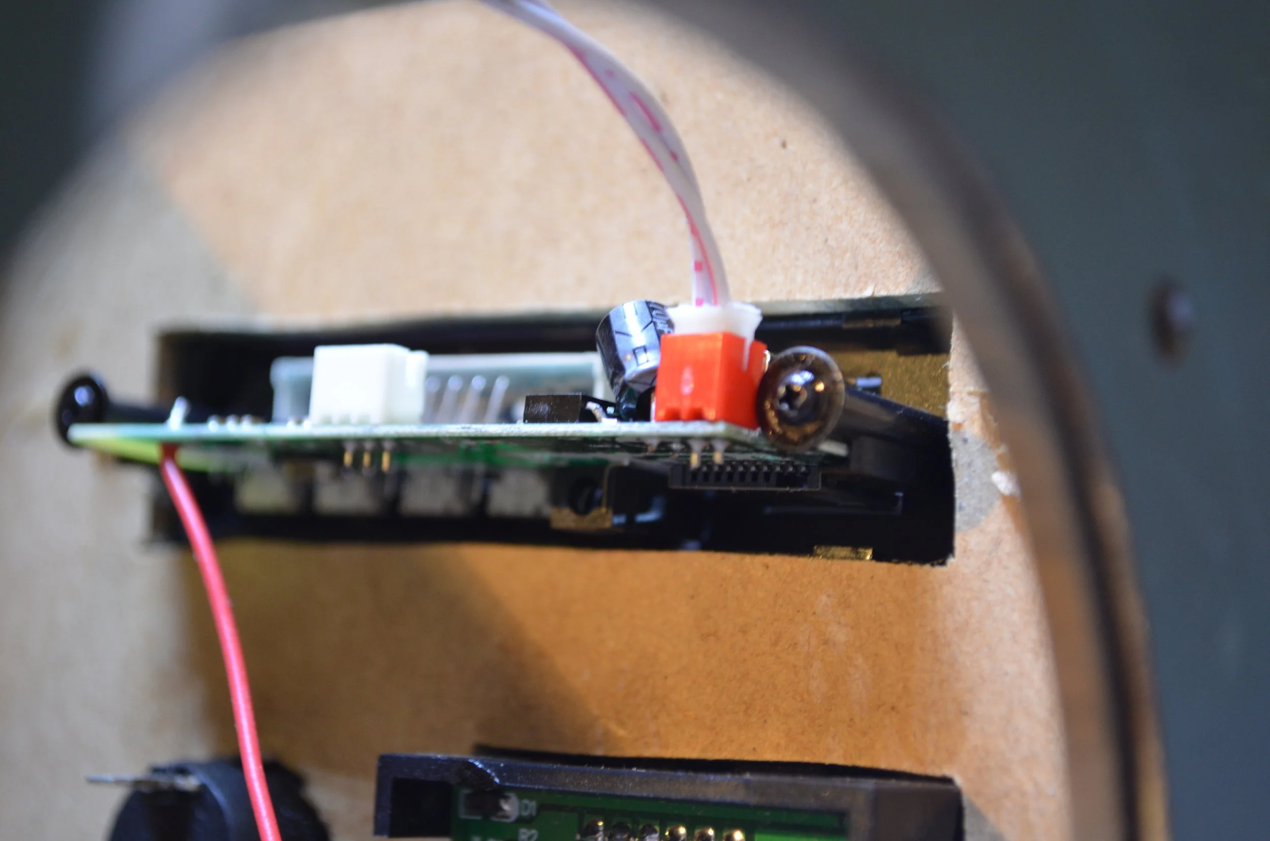
 
DSC_1641.JPG

Mount the Battery

The Battery will provide power to the Amplifier, the Voltmeter and the LED Control Panel. Mount the battery inside of the box, using Hot Glue or Strong double sided tape. To prevent a short circuit, place tape over the Battery Management System (The Green Printed Circuit Board).
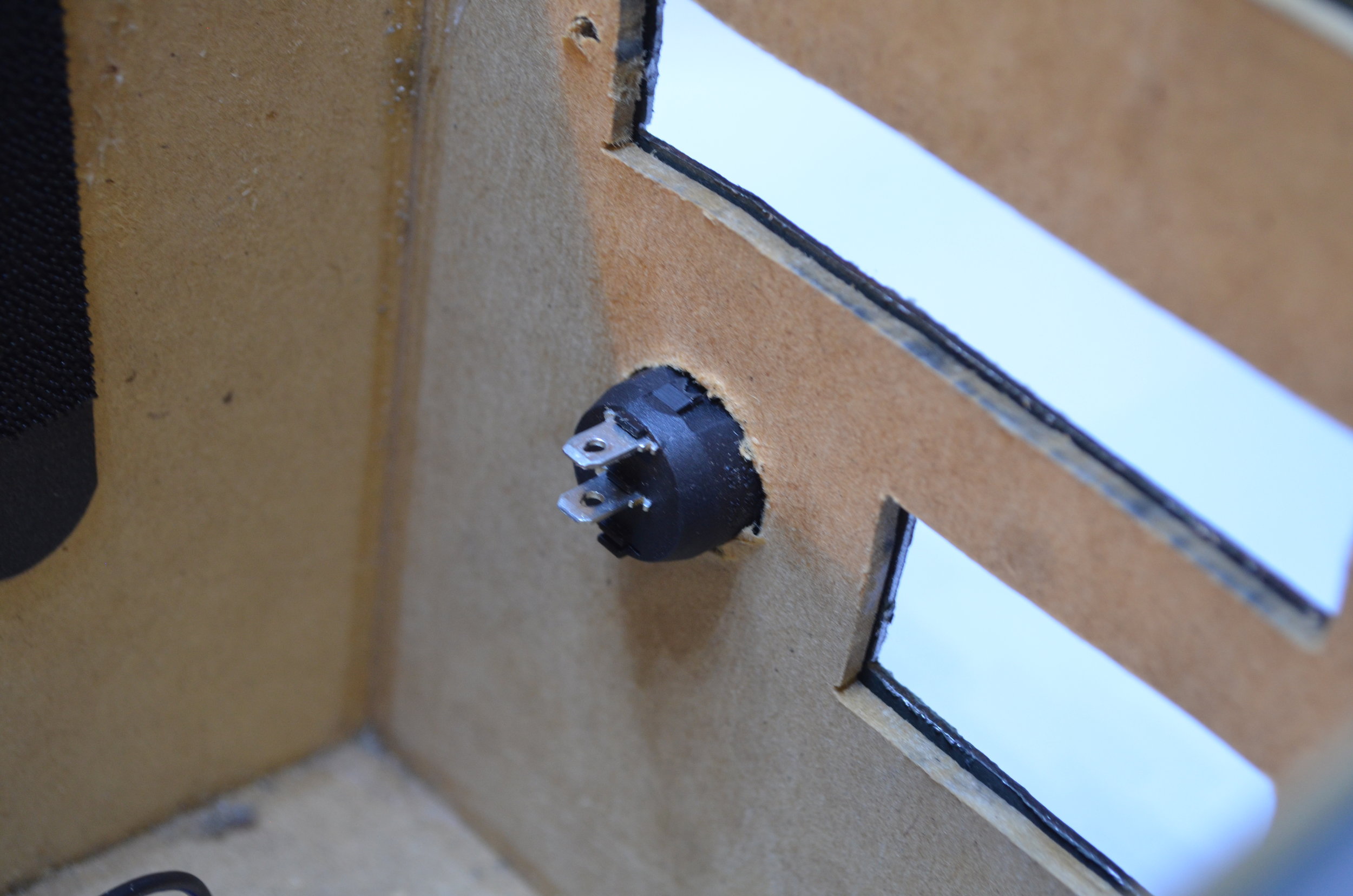
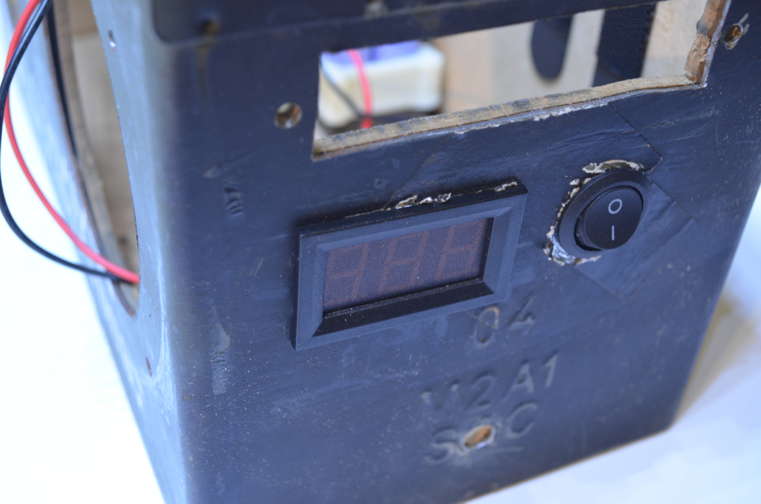
 
DSC_1644.JPG

Mount the Switch

In order to power the speaker on and off, we will use a switch to break the circuit. When the switch is on the circuit will be complete allowing electricity to flow through. A complete circuit (ON) is indicated by the Straight line (I) on the switch and an open circuit (Off) is indicated by a circle (O).

DSC_1646.JPG

Mount the Voltmeter

The Volt Meter indicates the Battery Voltage, and will give an indication into the state of charge of the Battery. The Voltage will range between 10 - 12 Volts. A full battery will be around 12 Volts, and a low battery will be around 10 Volts. If the Voltmeter is too tight to fit in the hole, cut off the wedge clips on Voltmeter.  

2021 - new speakers will have a round voltmeter, with positive and negative cables. The plus and minus will be located on the back of the voltmeter. These cables will be joined to the + and - on the screw terminal.

 
DSC_1653.JPG

Mount the LED Control Panel

Mount the LED Control Panel using the nuts and bolts provided with the Kit. All pre-cut kits have been tested with an LED Panel previously mounted flush inside the box. You may have to move the LED Control Panel around until it 'Clicks' into the hole. 

The LED Control Panel is the brains of the Speaker and will have Volume, Bluetooth, FM Radio and AUX Input functionality. 

 
DSC_1658.JPG

Mount the DC Socket

Mount the DC Socket into the Box. To do so you may need to file down the MDF wood inside of the box so that there is enough thread on the socket to fasten a nut. 

The DC Socket will be used to Charge the Speaker.  

2021 - New kits will have a Blue Module in between the battery and the DC socket. The blue module drops the voltage from 19V to 12.9 Volts to safely charge the battery.

Wiring the Positive DC Socket to either pole of the Switch.

Wiring the Positive DC Socket to either pole of the Switch.

Wire the Positive DC Socket to the Switch.

Wire the Positive of the DC Socket (The Red Wire) to the either pole of the Switch. To do this, slide the female spade crimp over the male terminal on the switch. 

 
DSC_1686.JPG

Wire the Switch to the Positive Bolt of the Terminal Bus.

Wire the opposite pole of the switch (that isn't wired to the DC socket) to the positive Bolt on the Terminal Bus. To do this, slide the female crimp over the male terminal on the switch. The Loop on the opposite end of the wire will go around the Positive bolt on the Terminal Bus. 

 
DSC_1690.JPG

Wire the Volt meter to the Terminal Bus. 

Wire the positive (red) and negative (black) cable of the voltmeter to the positive and negative sections of the Terminal Bus. 

The 2021 Kit will have a cables and crimps going onto a round voltmeter.


DSC_1696.JPG

Wire the LED Control Panel to the Terminal Bus.

Wire the LED Control Panel to the Positive and Negative section of the Terminal Bus. 

The Red Wire (positive) will go to the Positive Bolt, and the Black Wire (Negative) will be wired to the Negative Bolt on the Terminal Bus. 

2021 Kits will have a black chip, in between the LED module plug and the screw terminal. This little black chip with 4 wires isolates the 12V power supply to prevent any noise from occurring.

 
DSC_1670.JPG

Screw wires into the Amplifier

Screw the Positive and Negative Cables into the Amplifier. The Positive wire will be on the Left side of the Screw Terminal (if the Amplifier is facing upwards), and the Negative black wire will be screwed into the Right side of the Screw Terminal. The negative section of the screw terminal is indicated by the GND. 

Cut down the Speaker wires (Black and Green Wires inside Speaker Packaging) - but do not cut off the crimp terminals, as these will go into the Speakers.  

Facing upwards from left to right; The Left terminal will be the Right Speaker, and the Right Terminal will be the Left Speaker. One pair of wires will be screwed into each terminal. 

The First cable will go into the left terminal (right speaker). The Black wire (Negative) will be screwed into the left side of the terminal; and the Positive wire will be wired into right side of the screw terminal. 

 Orientation (from left to right; Black L-, Green L+, Green R+, Green R-)

 
DSC_1700.JPG

Mount the Amplifier into the Box.

To mount the Amplifier either use Double sided tape, Hot Glue or Screws. 

Amplifier wired to the Terminal bus

Amplifier wired to the Terminal bus

Wire the Positive and Negative of the Amplifier into Terminal Bus.

Wire the Red (Positive) and Black (Negative) cable coming from the top of the Amplifier to the Positive and Negative sections of the Terminal Bus.

 
DSC_1682.JPG

Wire the Battery to the Switch via the Fuse Holder

Place the fuse inside of the Fuse holder and screw fuse holder sections together.   

 
DSC_1699.JPG

Connect the Negative from the Battery to the Terminal Bus

Before you begin, make sure the switch is in the off position.  

Now that everything is in place, the last wire to be connected is the negative cable (GND) from the Battery Management System; on the battery. Connect the negative wire from the BMS to the Negative Bolt on the Terminal Bus. 


5.jpg

Connect 3P Audio Cable from Amplifier to LED Control Panel

Plug in the 3 Pin audio signal cable into the Amplifier and the LED Control Panel. This cable will send an audio signal from the LED control Panel to the Amplifier. 

 
4.jpg

Wire speaker cable from Amplifier to Speakers.

Wire the Positive and Negative Speaker cables (located on the bottom of the amplifier) from the Amplifier to the Speakers.