
There are two types of audio systems, stereo and mono. A stereo sound system has two independent audio channel signals, whereas a monophonic system reproduces multiple signals through one channel.
AMPLFY speakers are designed as a stereo sound system.
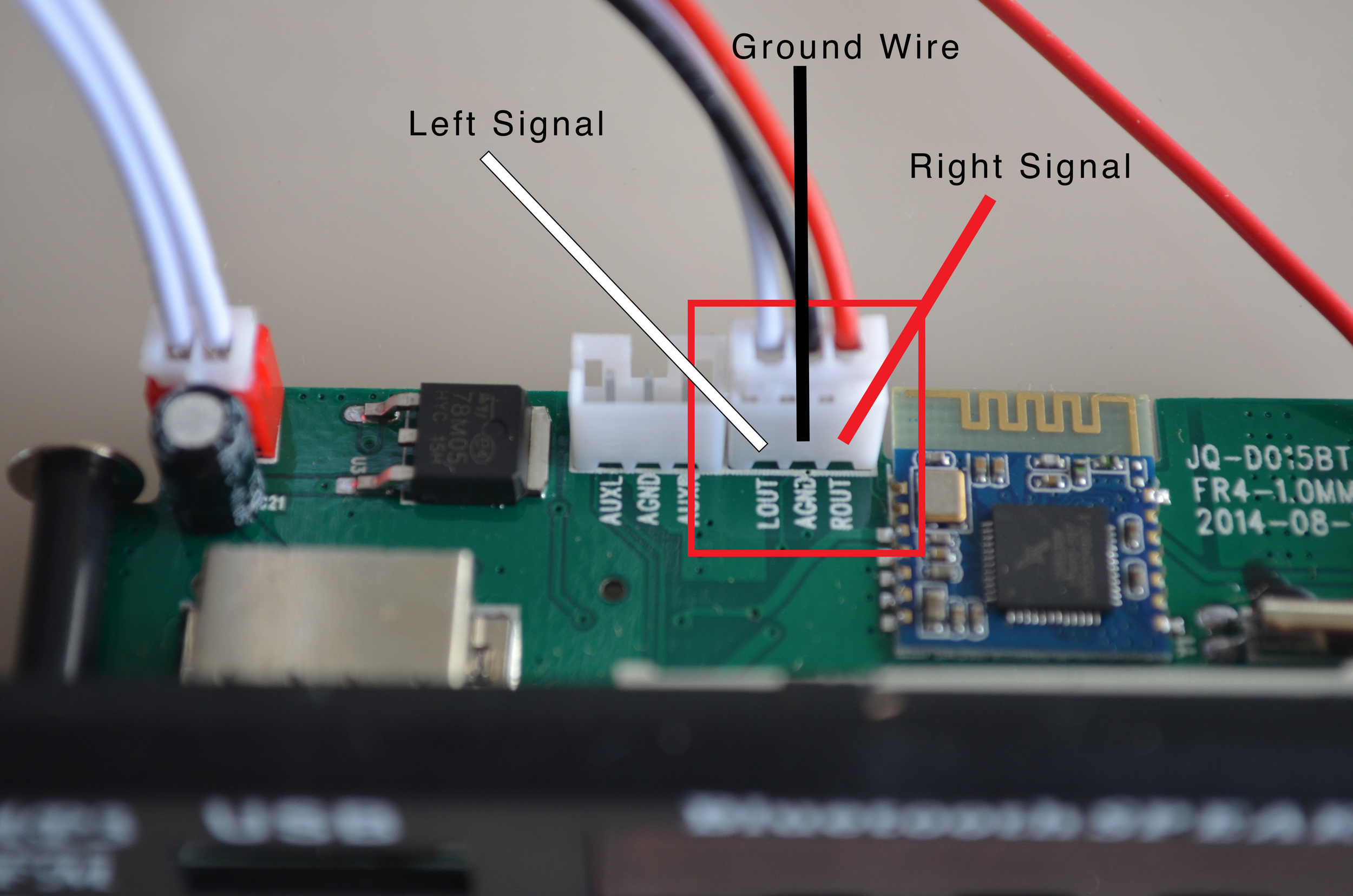
As such each speaker will be receiving an independent audio signal. The left speaker will be receiving a 'left' audio signal, whereas the right speaker will be receiving a 'right' audio signal.
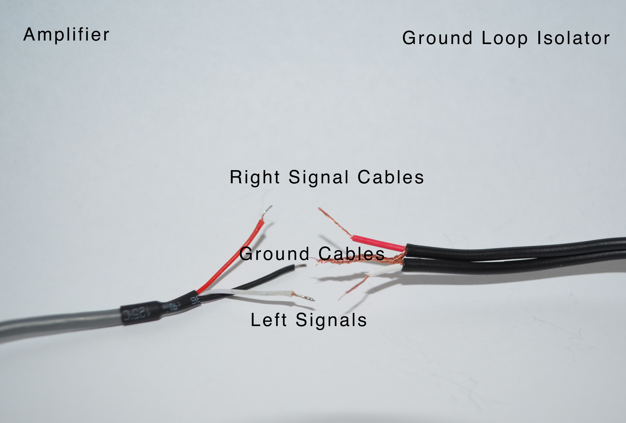
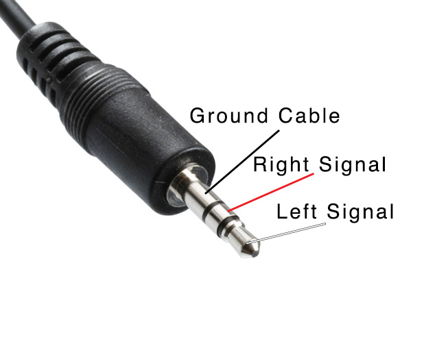
The amplifier receives the audio signal from a source (Phone or an MP3 player) via either an aux cable (pictured in the gallery below), bluetooth or an alternative medium and sends the left and right signal to the corresponding speaker. If we were to dissect the Aux Cable, there would be three wires - a ground cable (usually black or a shielded wire), a right signal cable (usually red) and a left signal cable (usually white or yellow).
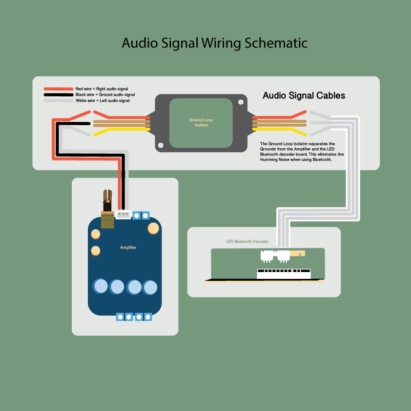
In order for the amplifier to receive an audio signal, the audio signal cables from the LED control panel must be wired to the audio signal cables of the amplifier. However, because we are connecting the 'ground' of multiple signals, a 'buzzing' noise occurs. Therefore, a ground 'loop' isolator must be wired between the audio signal cables of the LED Control Panel and the Audio Signal Cables of the Amplifier.
Update:
We have updated our LED Bluetooth Decoders to a newer version, which has the ground loop isolation function built into the chip. If your kit was purchased before Nov 2016 and has the ‘Ground Loop Isolator’ included in the kit, you will still need to follow this step. If you have the newer kit, instead of a ground loop isolator you will have a 3-pin cable, which will connect directly from the Amplifier to the LED Bluetooth Decoder. See the picture below.

If you have the older version of the Kit with the 'Ground Loop Isolator', follow the steps below:
The following diagram illustrates how the Ground Loop Isolator is connected to the LED Control Panel and the Amplifier.
Steps:
- Unscrew the housing of Ground Loop Isolator (to free up extra space).
- Cut the red and white plugs off of Ground Loop Isolator.
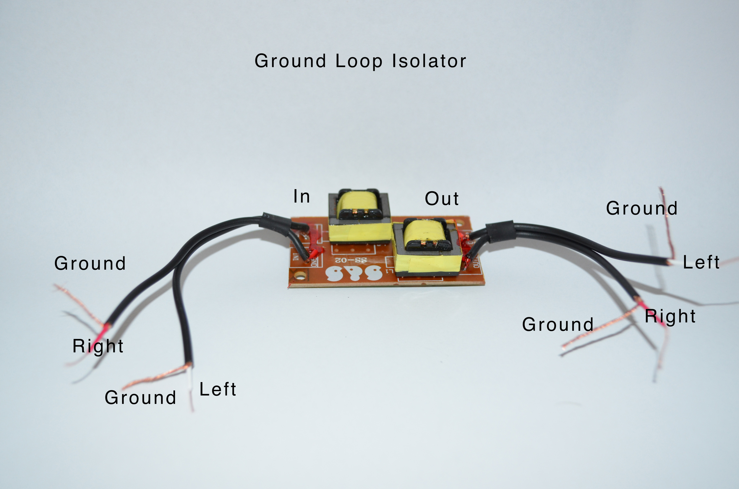
- Expose all of the wires (There should be one red, white and two shielded wires on either side of the Ground Loop - see pictures below).
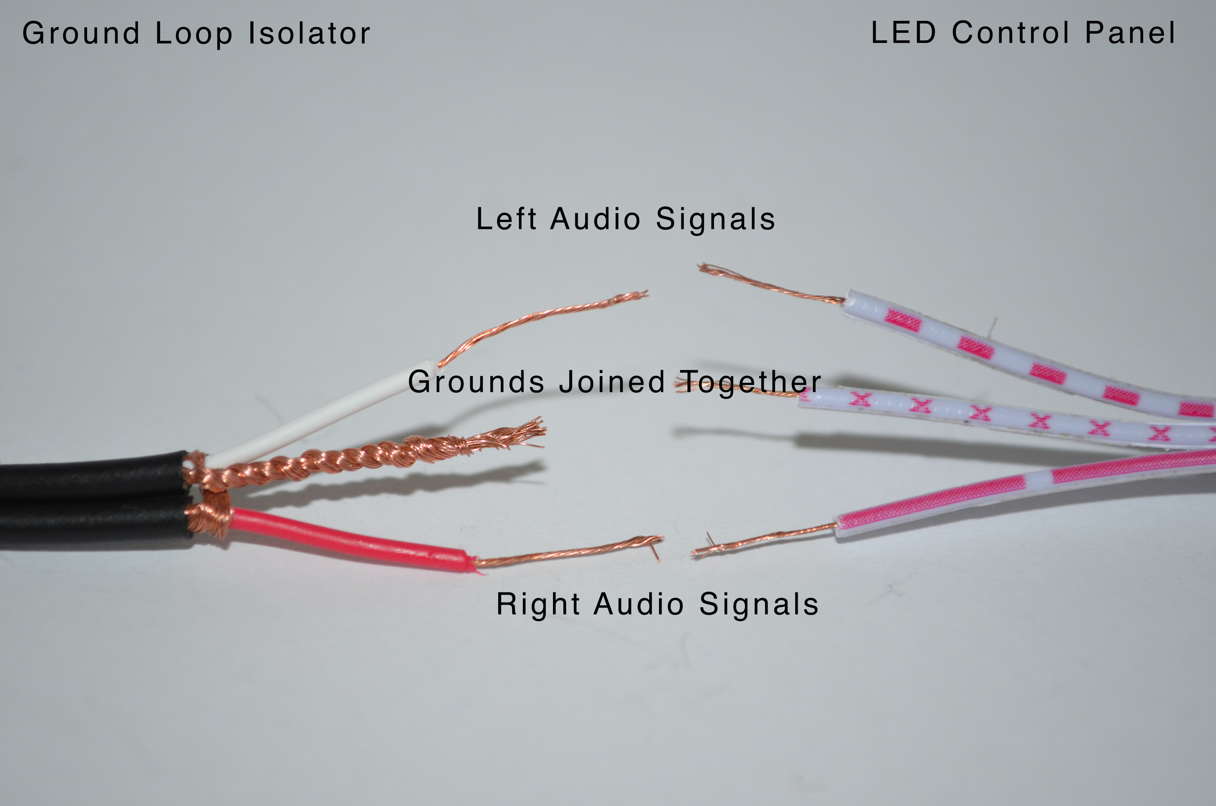
- Twist the Ground Cables of the Ground Loop Isolator together (pictured below).
- Connect the Left, Right and Ground cables of the Ground Loop Isolator to the Left, Right and Ground cables of the LED Control Panel. Make sure you connect the cables from the 'IN' side of the Ground Loop Isolator to the LED Control Panel. The 'IN' is marked on the ground loop Isolator.
- Connect the Left, Right and Ground Cables (on the 'OUT' side) of the Ground Loop Isolator to the Left, Right and Ground Cables of the Amplifier.
- Cover Exposed wires with Heat shrink.
Joining wires:
In order to establish the strongest connection it is best to solder wires together and cover the exposed wires with heat shrink. However if you don't have a soldering iron, you can connect the wires using both female and male spade crimp terminals or a small screw terminal.
The video below demonstrates the entire process of wiring the audio signal cables.