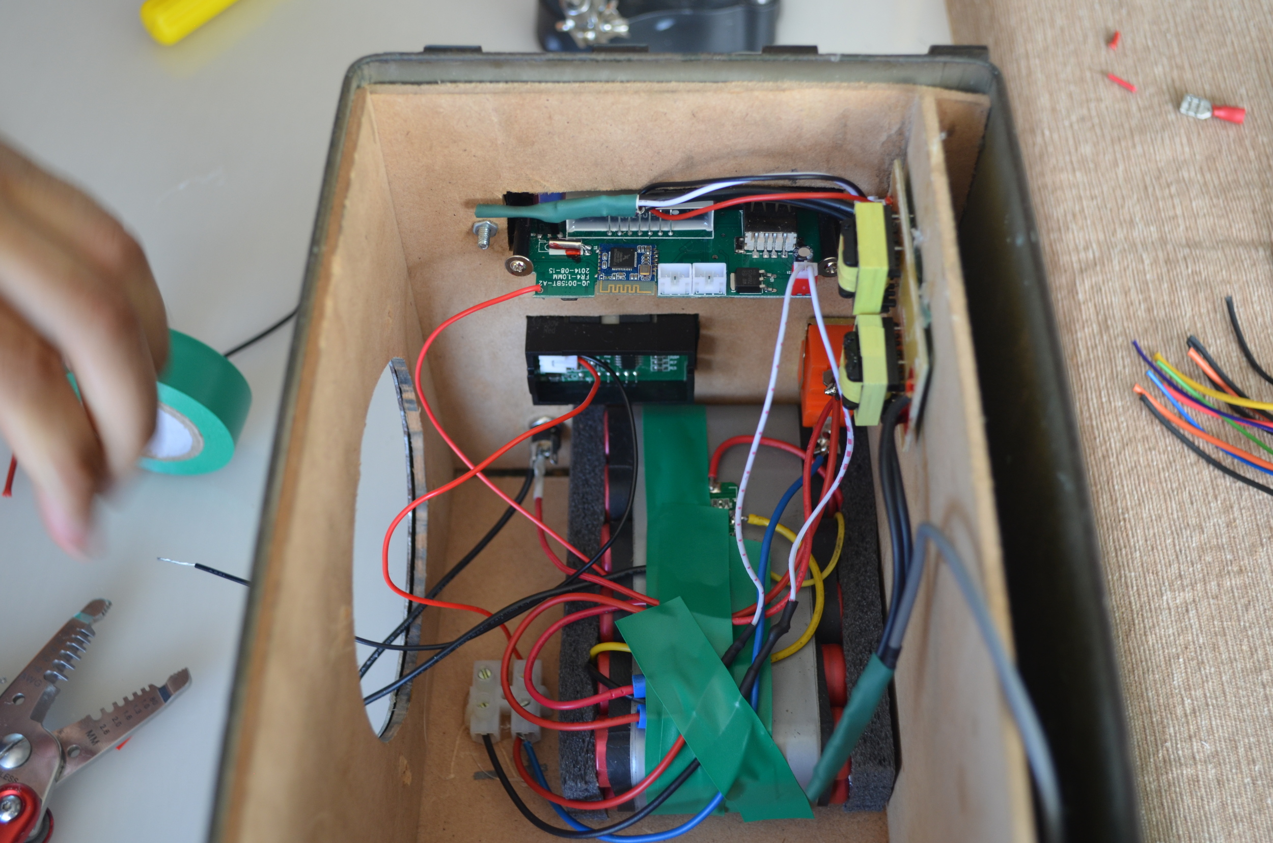

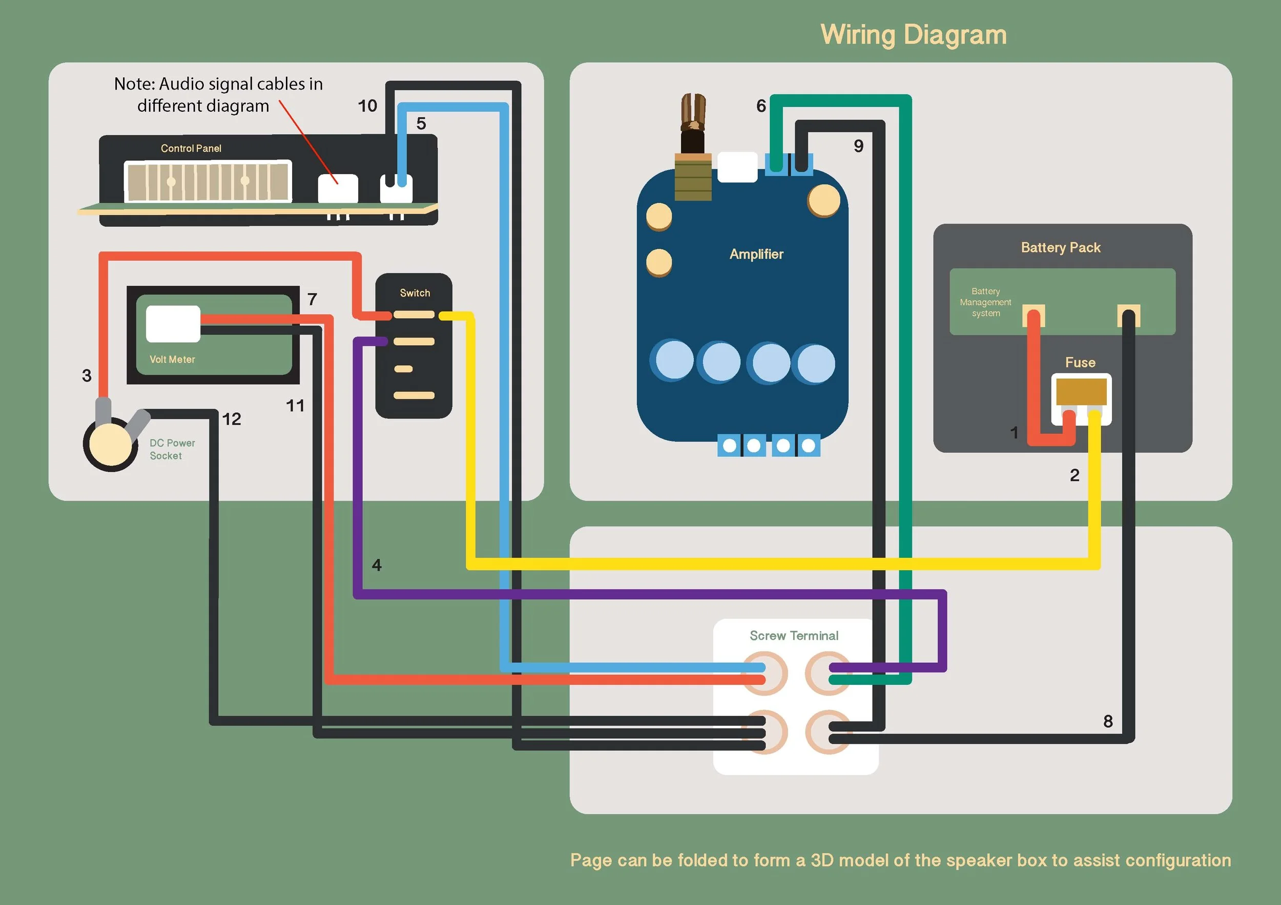
The Wiring Process:
The numbers listed in the steps below correspond to the numbers in the diagram above.
- Wire the P+ (Wire 1) on the Battery Management System to either pole on the 5 amp fuse.
- Wire the the opposite pole of the (wire 2) Fuse and the positive (red) cable (Wire 3) from the DC power socket to the to the top pole of the switch. In doing so, we are connecting the DC power socket directly to the Battery. This means the battery will be able to be charged, despite the switch being turned on or off.
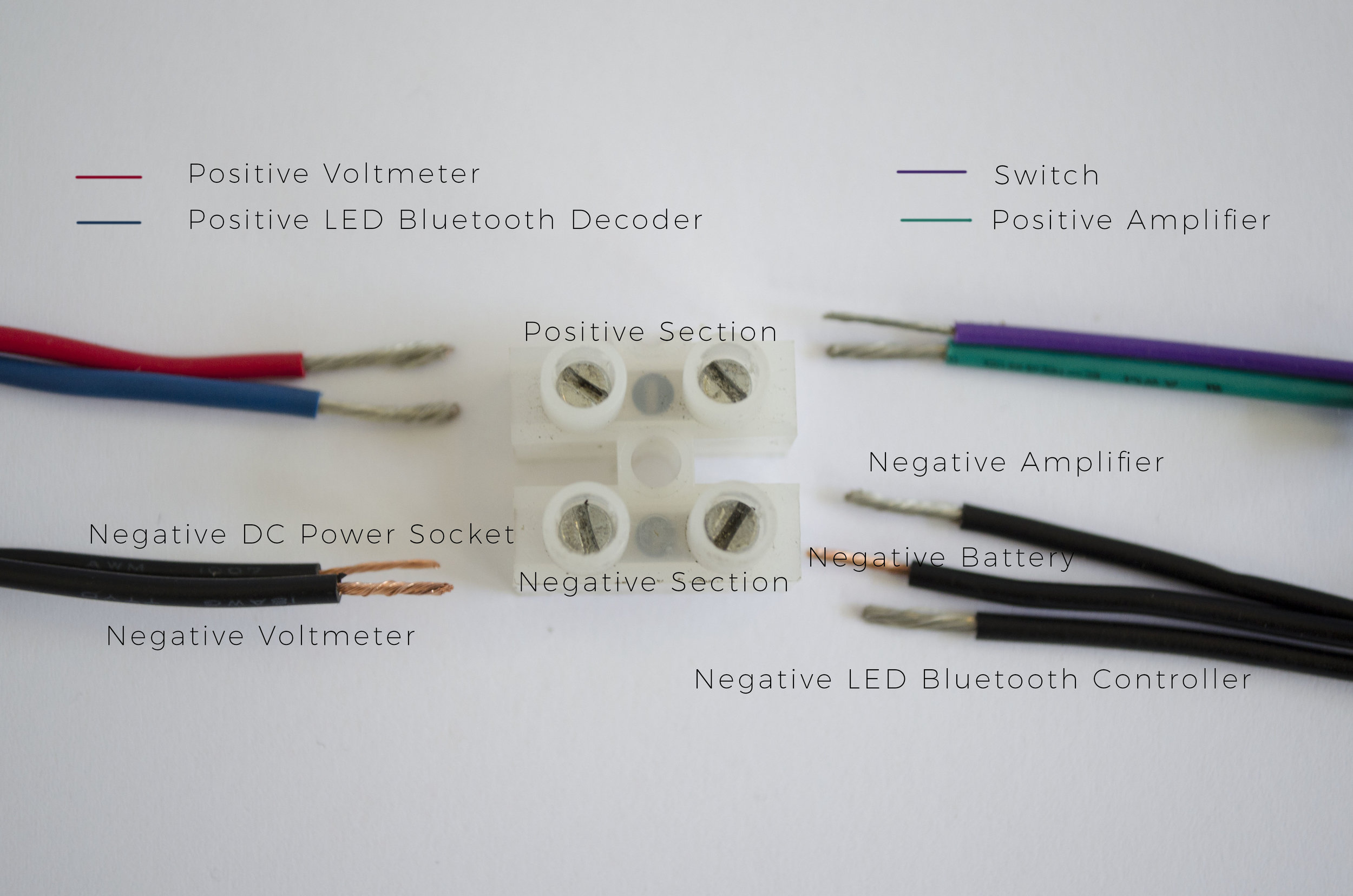
- Wire the Second Pole of the Switch (Wire 4) to the positive section (+) of the screw Terminal. You will need to designate a positive and a ground (negative) section to the screw terminal. In the Diagram the section with the red, blue, purple and green wires, is the positive section. The negative section has all black wires.
- Wire the Positive LED Control Panel (Wire 5 - Blue) and the Positive (Wire 7 - Red) of the Voltmeter together and then screw the wires into the positive section of the screw terminal. If needed extend the wires by adding another wire and join the wires with solder or with a male / female crimp.
- Cut an additional piece of wire (6 - Green), which will extend from the positive 12+ on the Amplifier to the Screw Terminal. Wire this cable together with the purple wire (4) from the switch to the screw terminal.
- Wire the Ground of the Battery (B-) (Wire 8 - Black) on the BMS to the Ground (-) section of the Screw Terminal.
- Wire the Ground of the Voltmeter (Wire 11) - Black) and the LED Control Panel (Wire 10) to the 'Ground' section of the Screw Terminal.
- Wire the Ground of the DC socket (Wire 12 - Black) to the Ground (-) section of the Screw Terminal.
- Wire the Positive of the Amplifier (Wire 9 - Black)
You will need to cut four additional wires; if you don't have any additional wire you can use the speaker wire included in the kit. The wires you will need to cut are numbered 2, 4, 6 and 9 in the diagram. The colour of the wires in the diagram may not correspond to the wires in your kit.
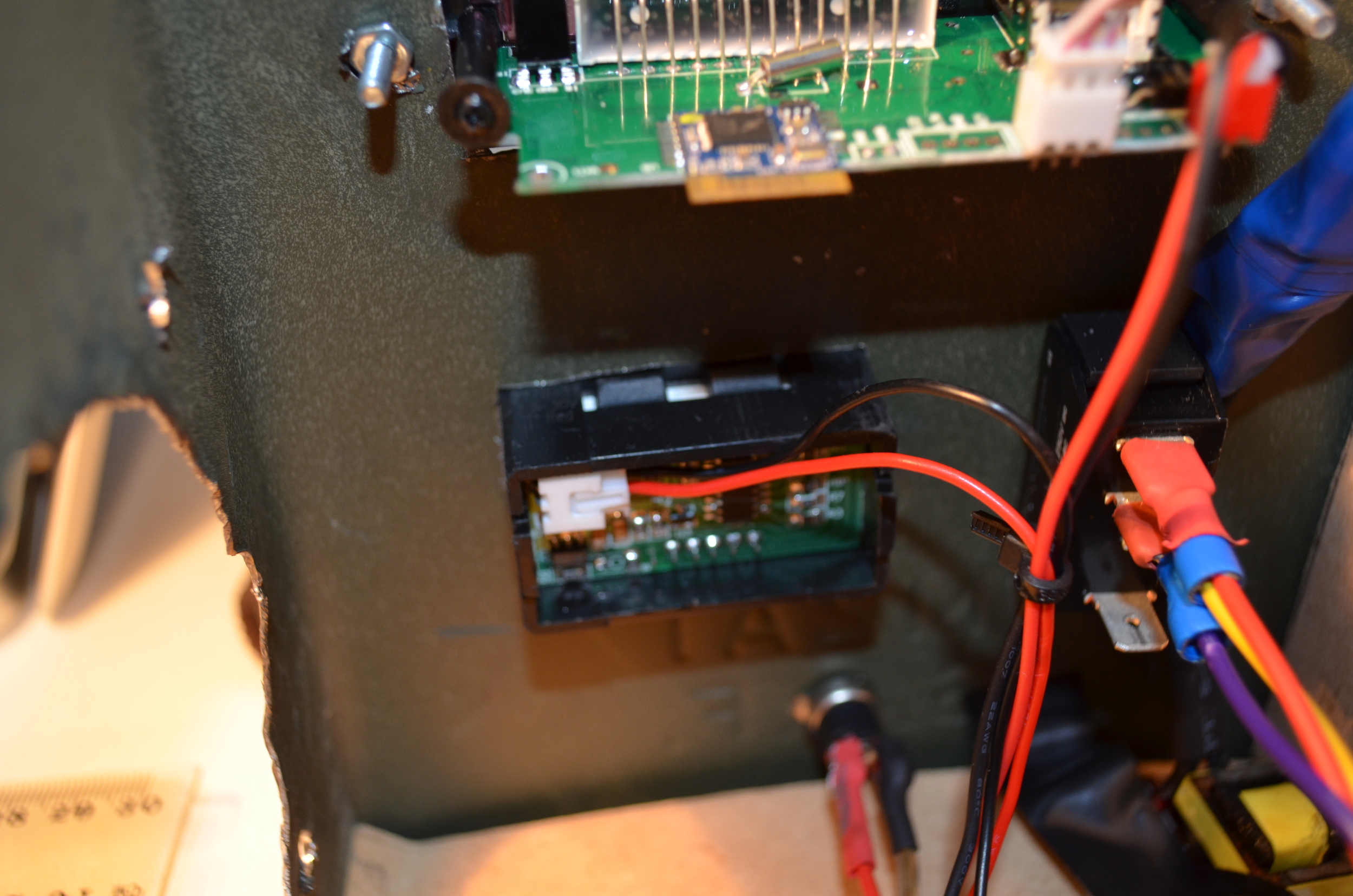
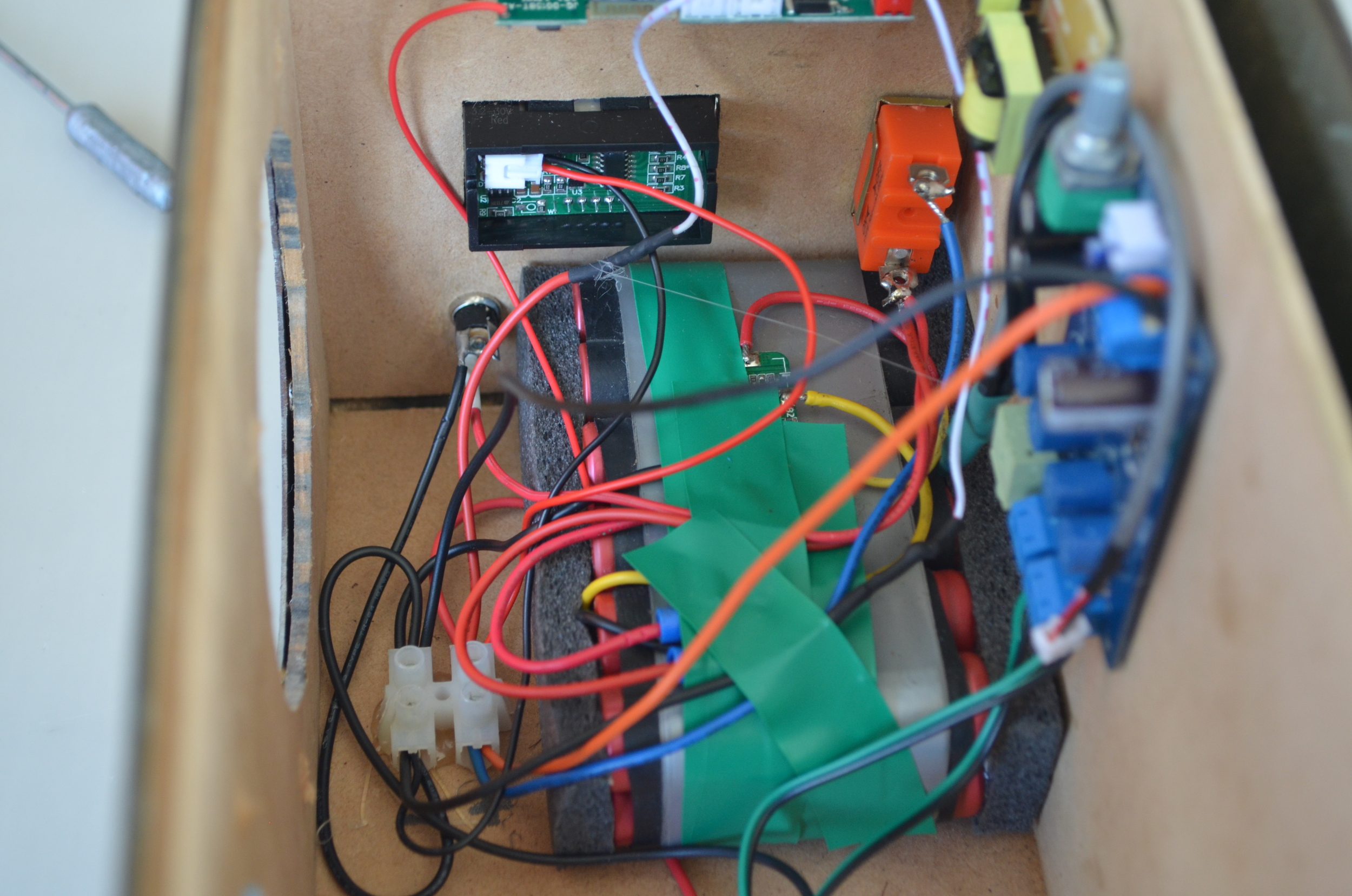
Screw Terminal:
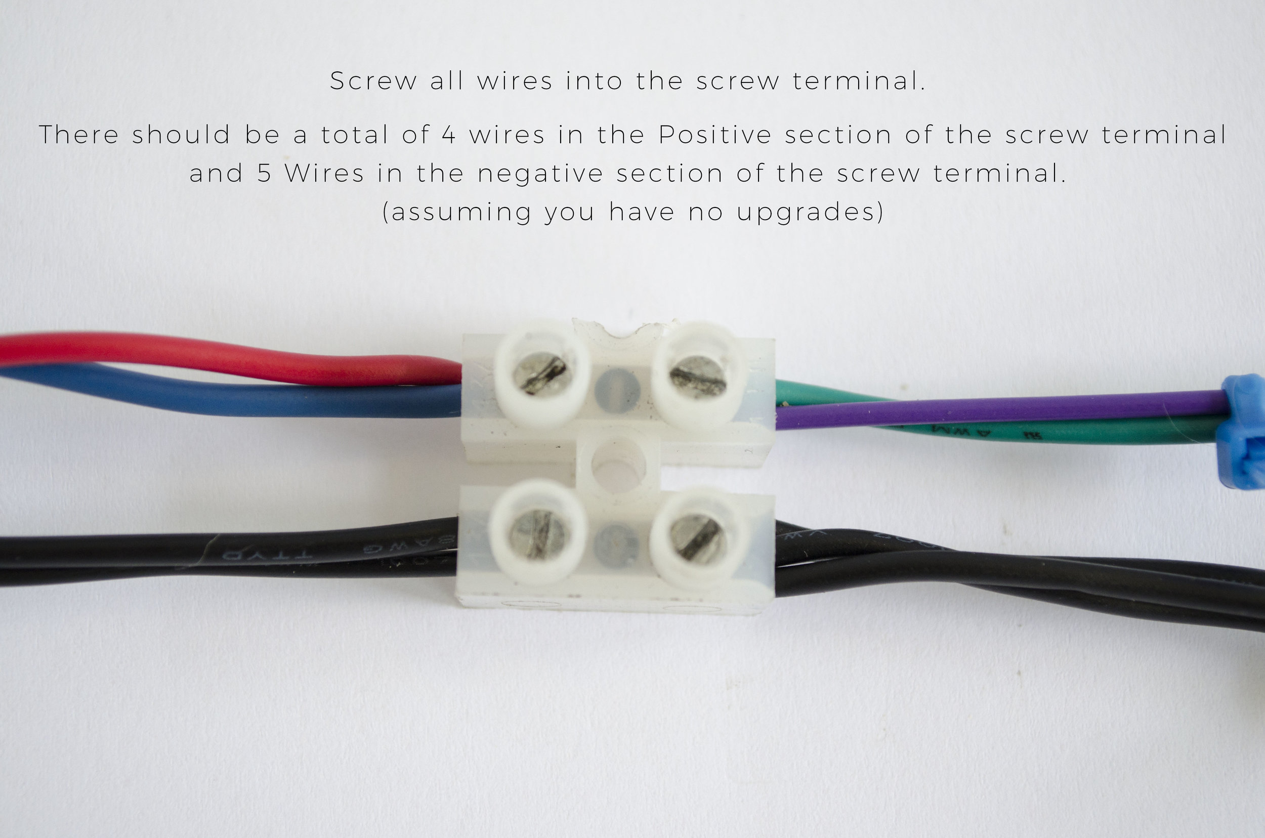
A good way to check you have included all of the wires, is to count the number of wires in the screw terminal. if you have wired it correctly you should have 4 wires in the positive section and 5 wires in the negative section. If you are wiring in a phone charger, you will have an extra wire in each positive and negative section of the terminal.
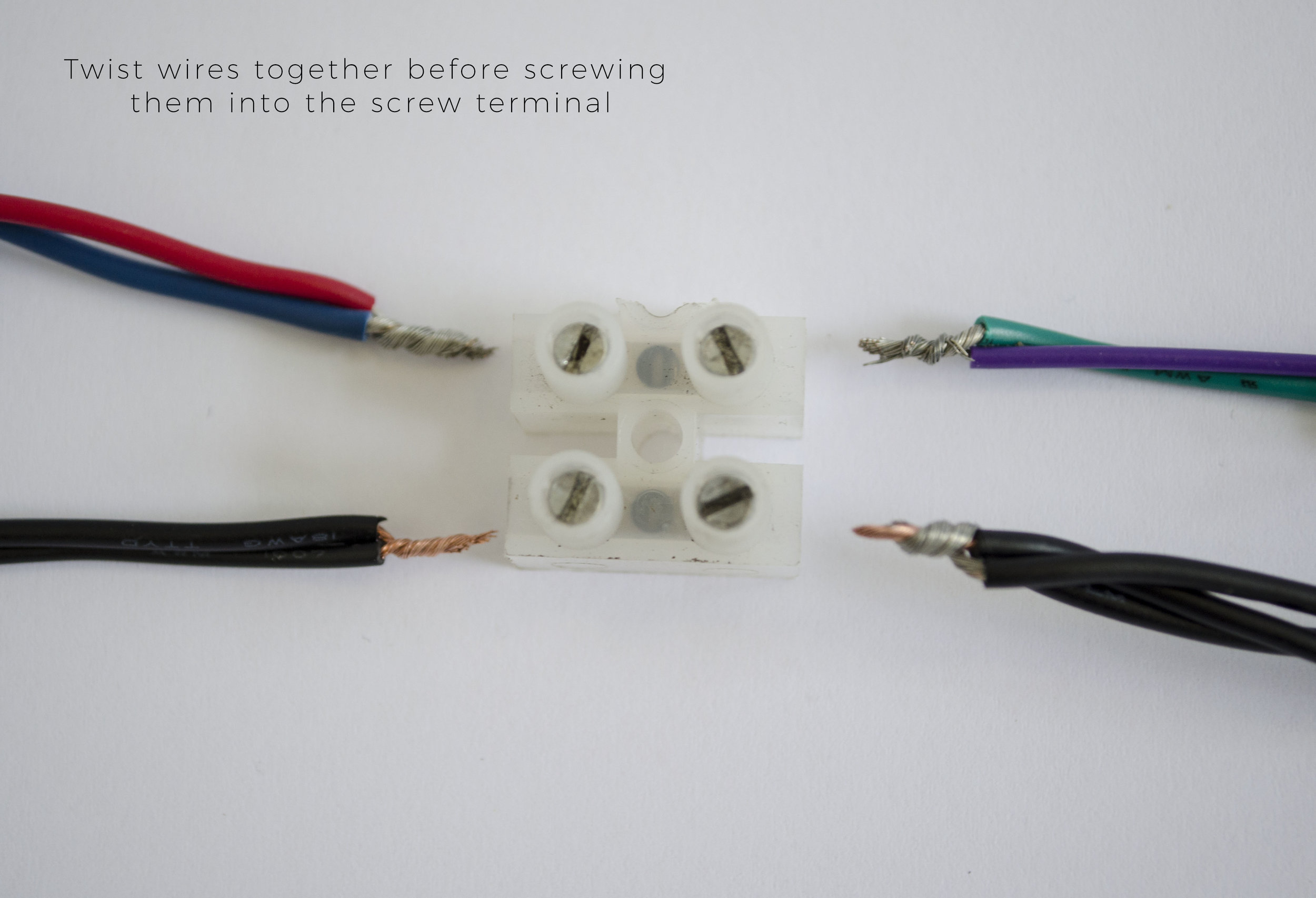
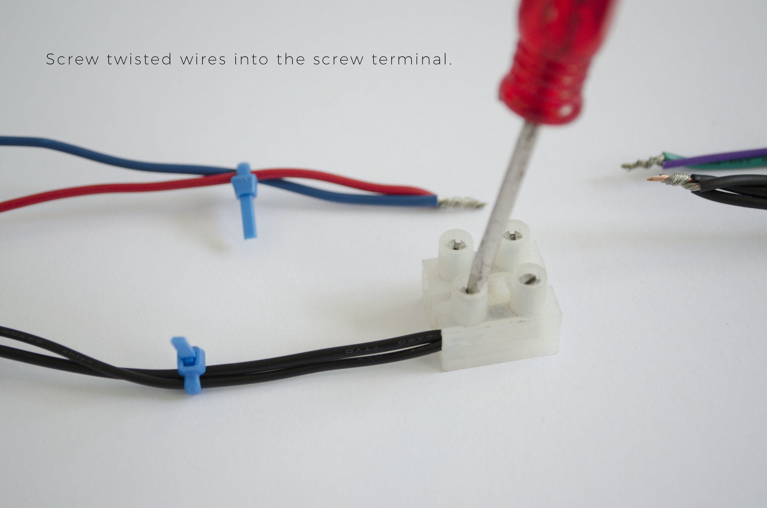
The purpose of the screw terminal is to connect a number of different wires together without soldering or using crimps. To use the screw terminal unscrew the screws in the terminal so that there is enough room for the wires to be slotted into each section. Once the wires are in the terminal tighten the screw onto the wires to ensure they don't come out over time.
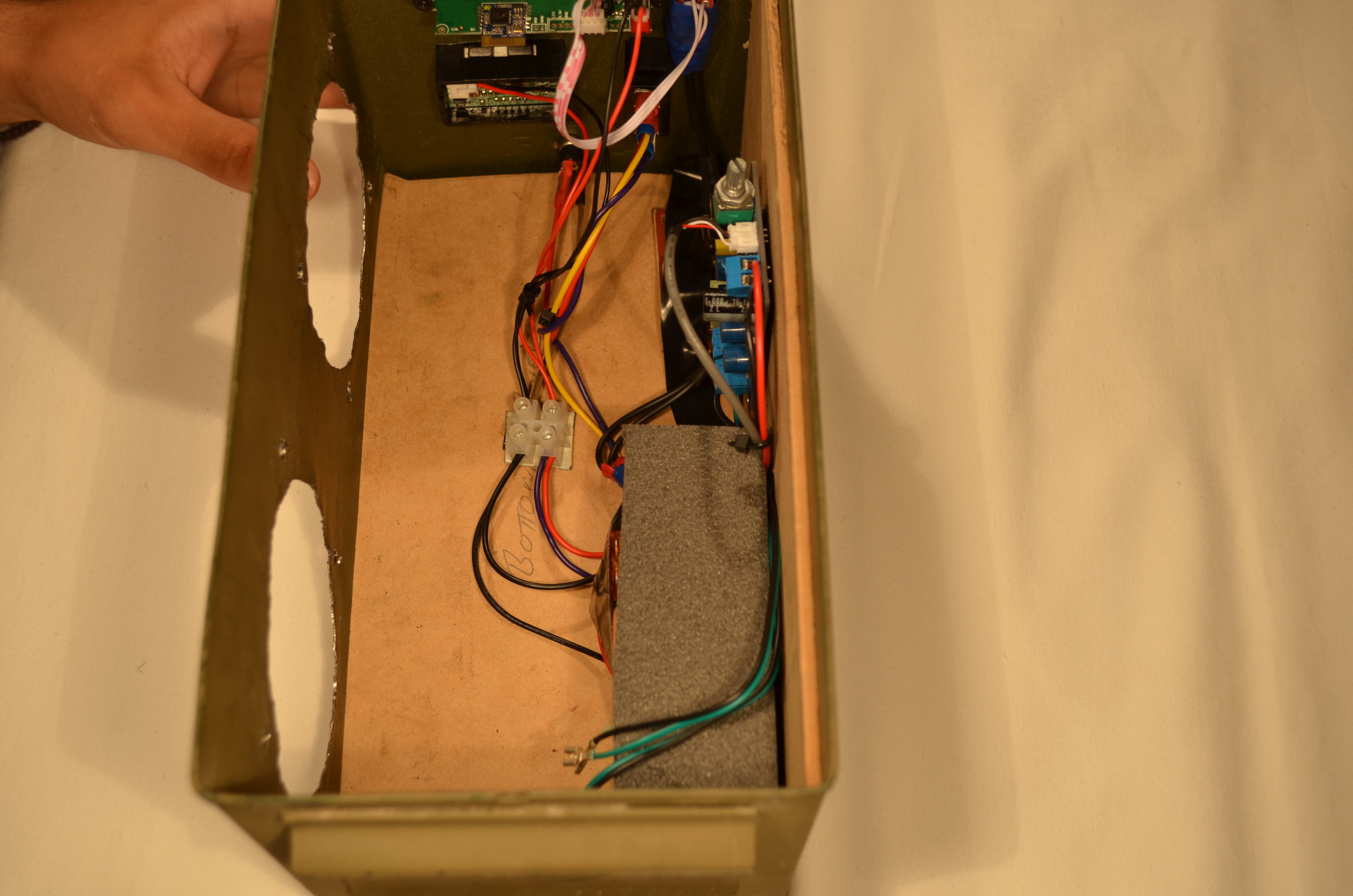
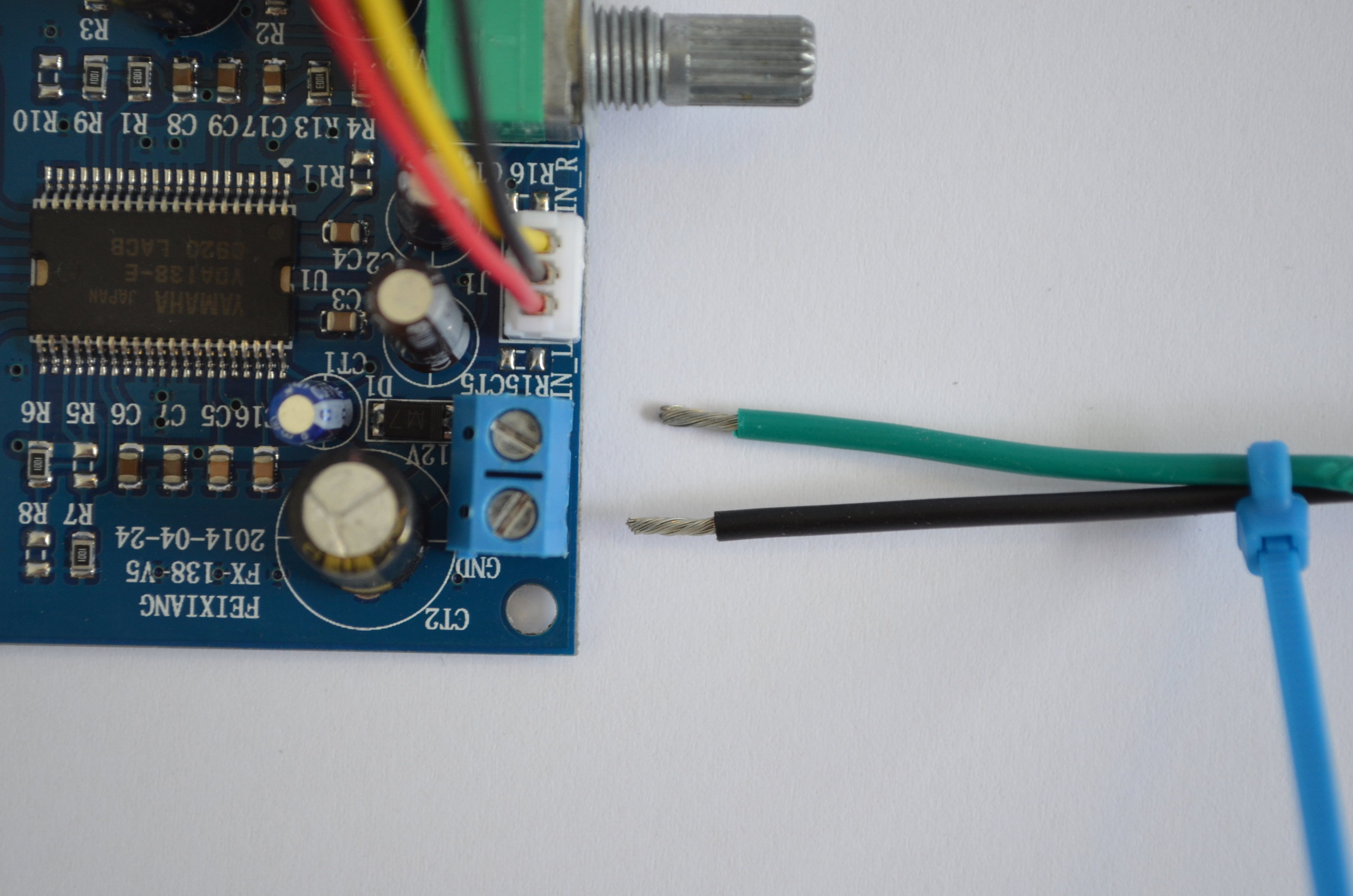
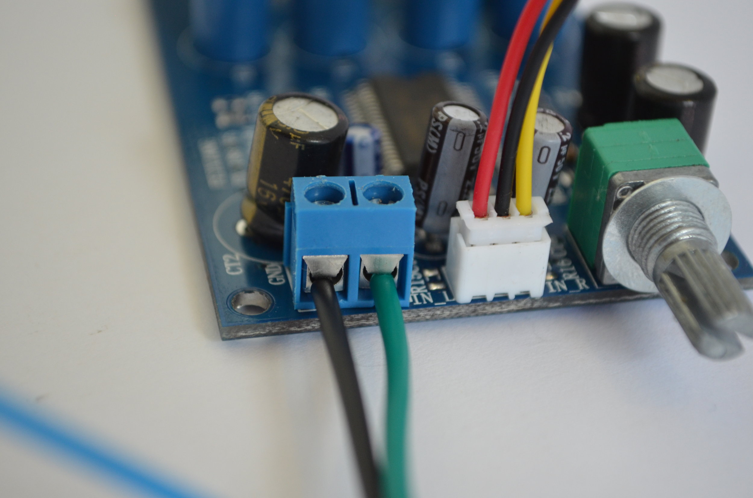
Amplifier:
In order to power the Amplifier, you will need two wires coming from the screw terminal into the blue screw terminals on the amplifier. This is represented by wire 6 and 9 on the wiring diagram above. To use the screw terminal on the amplifier loosen the screws, slot the wires into the appropriate terminal and tighten the screws onto the wire. Make sure you do not reverse the polarity (ie. positive in negative), otherwise you risk damaging the amplifier. The negative on the Amplifier is represented by the 'GND' next to the Screw terminal and the positive is represented by the '12V'.
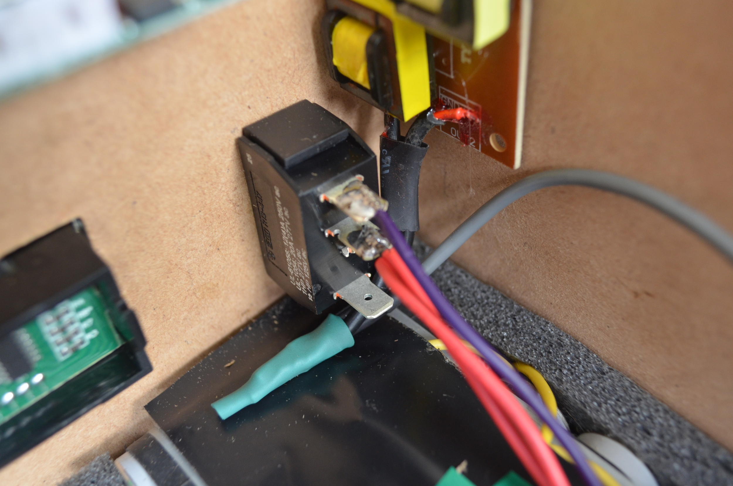
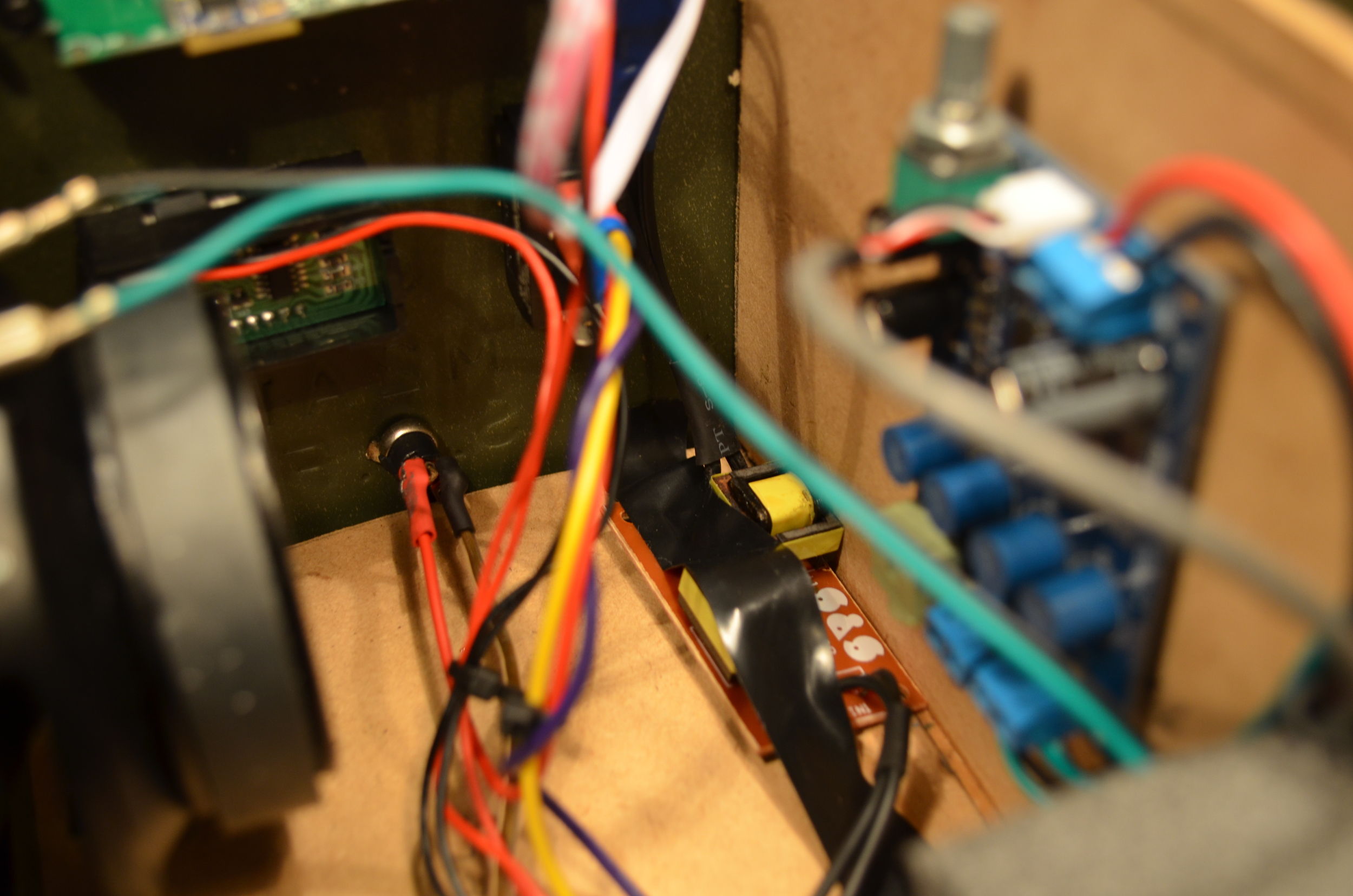
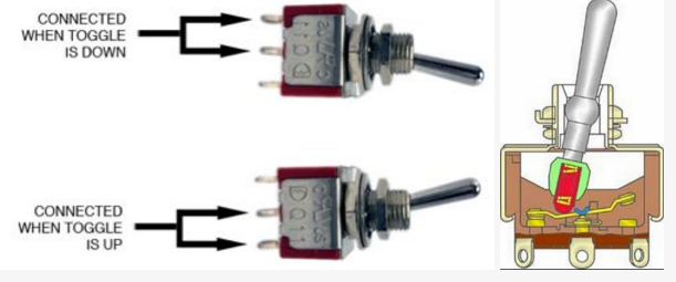
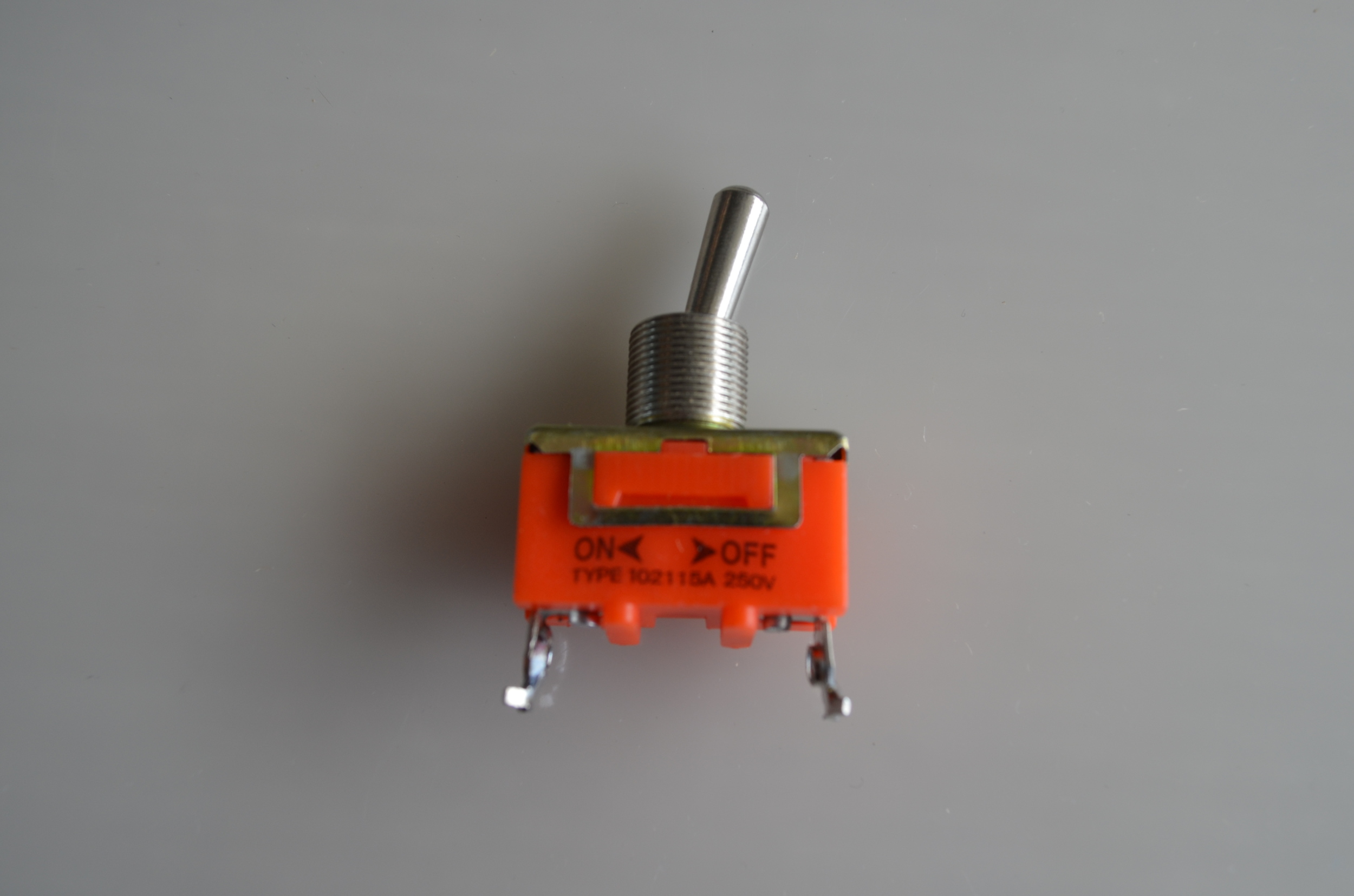
Orange Switch:
Newer kits are likely to have an orange switch, rather than the switch pictured in the diagram. Instead of having three poles, the orange switch will have two poles. The two poles act the same as the first and second pole pictured in the diagram. The purpose of the switch is to disconnect / connect the power cable from the battery to all of the powered components.
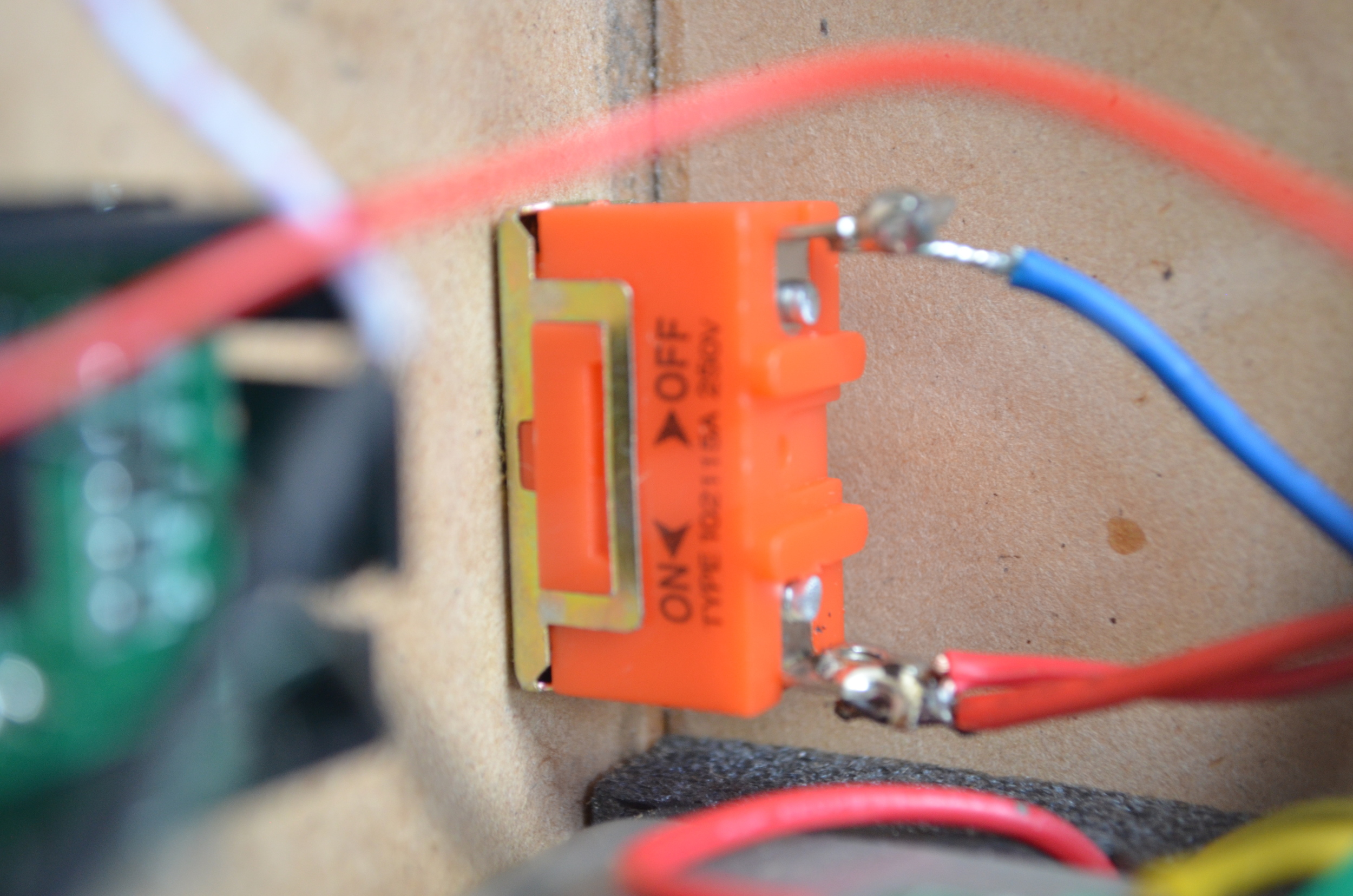
Simply connect one wire to the top or bottom pole of the switch, which will then be directed to the positive section on the screw terminal (represented by the purple wire 4 in the diagram). On the opposite pole of the switch, you will need to connect two wires together. One wire will be from the battery, represented by the yellow wire (2) and will be connected to the red wire (3) from the DC power socket.
To connect the wires to the switch, you can either screw on a loop terminal or solder the wires directly to the switch (like the picture below).
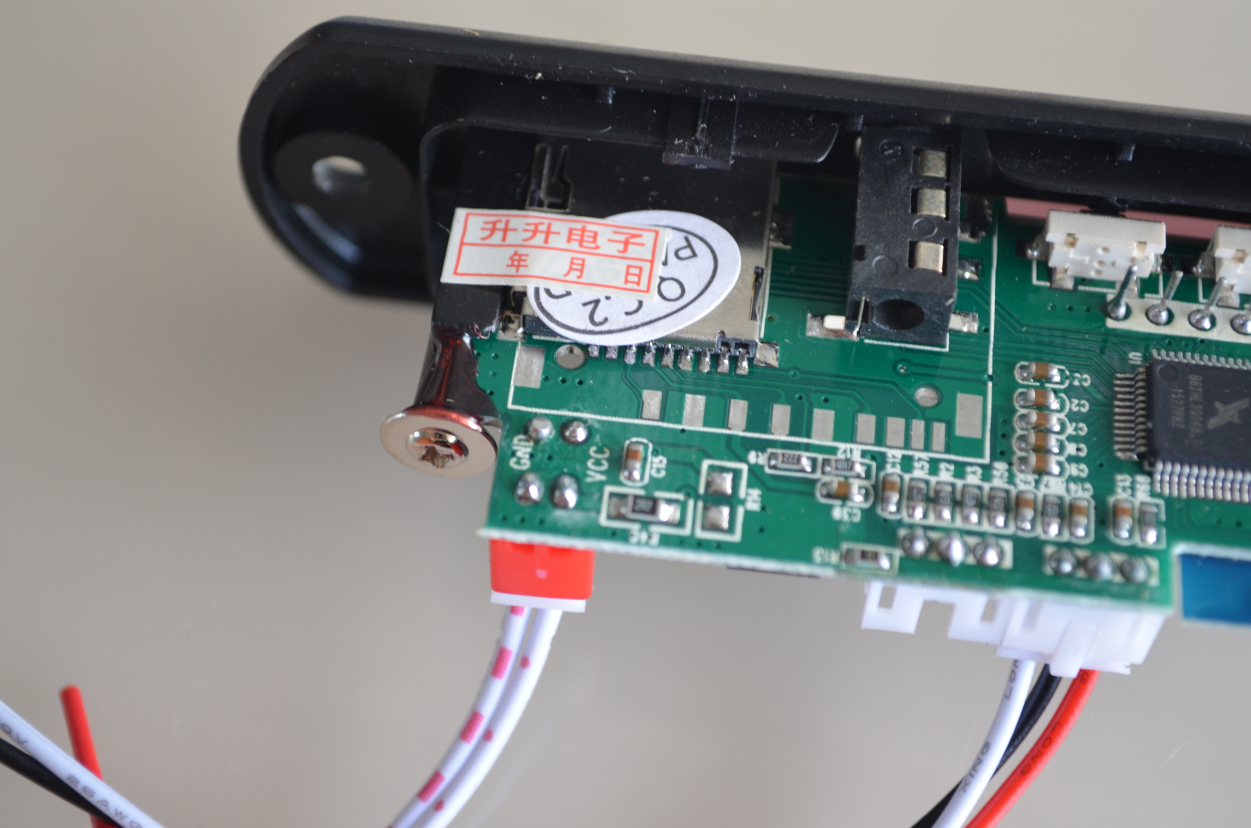
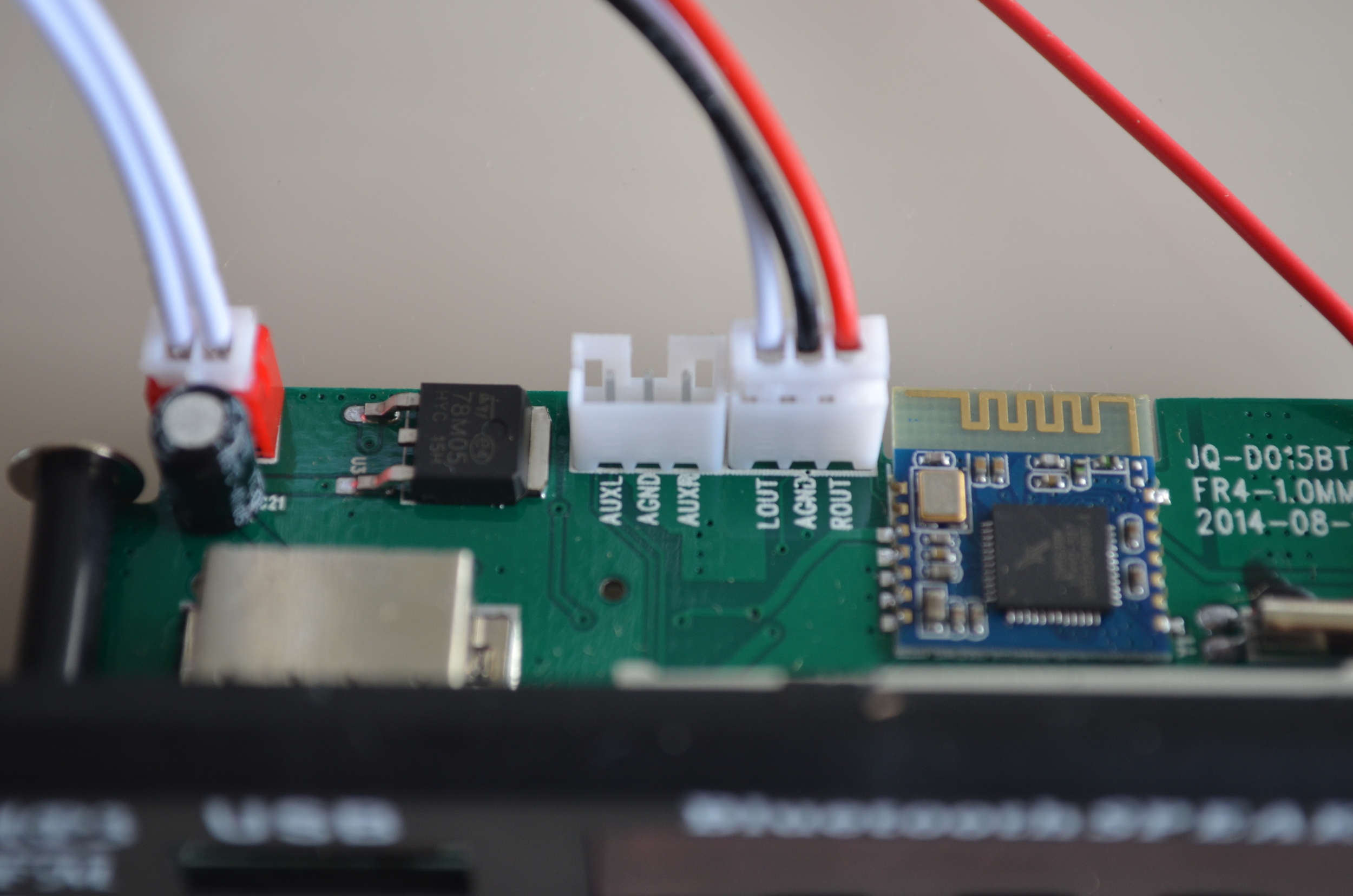
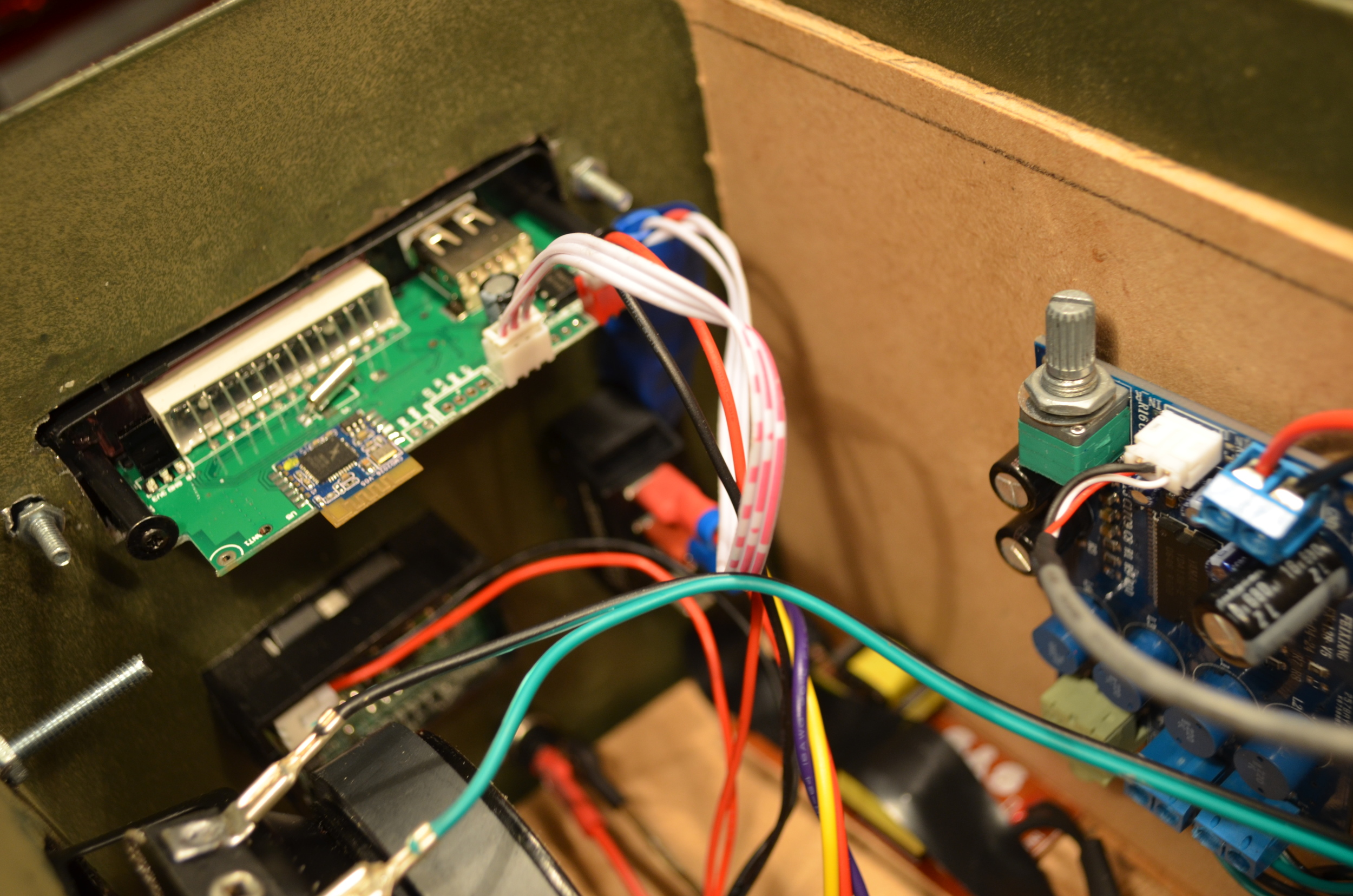
Wiring the LED Bluetooth Controller
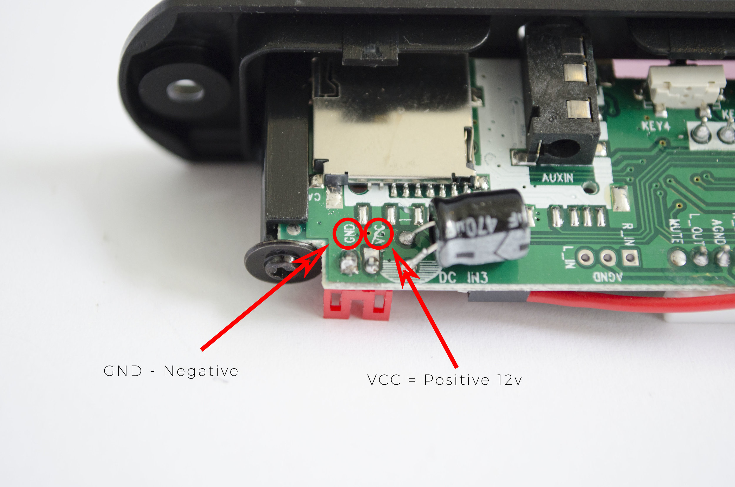
The most common problem when putting together the speaker is accidentally reversing the polarity of the 'LED bluetooth Controller' module - If you do this the chip will start to smoke. Be very careful when connecting this module. The positive and negative input of the module is marked with 'GND' and 'VCC' on the opposite side of the module (Ie. below the red clip). Triple check that you are wiring the correct wires from the module into the appropriate section of the screw terminal (+ / -). Make sure that you are wiring the 'VCC' wire to the positive section of the screw terminal and the 'GND' to the negative section of the screw terminal.
ADD ONS: Phone Charger
12 Volt Charging Socket:
- Wire the Positive Pole of the 12v Charging Socket to the Positive section of the Screw Terminal. The positive pole on the 12v Charging Socket is the 'middle' pole.
- Wire the Ground Pole of the 12v Charging Socket to the Negative section of the Screw Terminal. The Ground pole, is the 'outer' pole.